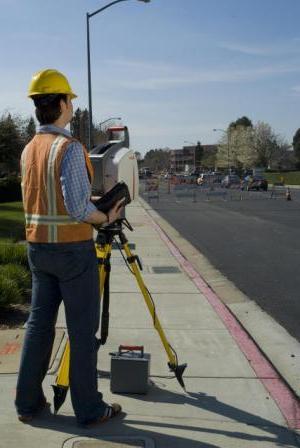
Whether a surveyor is measuring the topography of a site or the layout of a building, the general principle is much the same; essentially it is about measuring between points and combining this data to produce a composite drawing.
If the items being surveyed are assumed to be in a flat plane, i.e. no change in relative level, (referred to as the “Z” co-ordinate in Cartesian Co-ordinates), then a two dimensional (2D) plan can be produced by measuring between the features present (i.e. as termed “X” & “Y” co-ordinates in Cartesian Co-ordinates). In certain circumstances this can be carried out successfully by measuring between features with a tape measure, but this can become difficult once awkward angles are experienced, e.g. out-of-square rooms in a house etc..
However, if there are level changes to also be considered, then the only accurate way to survey is in three dimensions (3D), (i.e. “X”, “Y” & “Z” co-ordinates in Cartesian Co-ordinates). These co-ordinates are referred to by surveyors as “Easting”, “Northing”, & “Level” respectively. A surveying instrument is required to do this accurately.
 The survey methodology used is to survey each feature by observing each point using the latest computerised theodolites (optical survey instrument); referred to as “Total Stations”. This is basically done by walking across the site and taking readings by observing every feature required. Each feature type surveyed has a unique feature code that is recorded with the measured data; e.g. kerb, manhole, spot level, fence line, etc.. Attributes such as feature size can also be recorded. Specialist software combines all this data to produce a survey drawing.
In principle, this is carried out by setting-up the instrument over a known reference point (referred to as a “Survey Station”, or “Control Station”), and observing each feature with the optical instrument. A network of control stations is established, and these are related to each other by observing between these points. This is referred to as a “traverse”. Typically, this will be looped back onto itself, to ensure accuracy. This is referred to as a “closed traverse”. Features are then surveyed from these known points. (Note: If a long line of control points are established without any cross-checks or ties back to known points, then gradual inaccuracies can creep in; therefore a closed traverse is usually recommended).
Traditionally this survey process has been a two person operation, where one person held a prism (on a pole/staff) over each feature required to be recorded, and the other person would take a reading to the prism by focusing on it through the optics of the instrument. The height of the instrument on its tripod and the height of the prism on the pole will have been measured in advance and recorded. The instrument records bearing & distance for each surveyed feature. Specialist processing software computes this information and data, and produces a structured computer drawing of the site; which can be viewed on screen in 3D.
Total Surveys use the latest generation of Robotic “1-Man” Total Stations. As the name implies, these instruments only require one person to operate. The surveyor sets up the instrument over the control station, and then carries out the survey work by walking the site with the survey prism & pole. The instrument tracks the prism automatically, and the data recording and coding carried out by the surveyor is communicated by radio link between the instrument and the data logger which is connected to the prism & pole.
The instruments used by Total Surveys also have “non-contact” Electronic Distance Measuring (EDM) technology. These are often referred to as “Direct Reflex” or “DR” instruments, and these utilise an advance pulse measurement technique. This enables a surveyor to survey remote features without the need to gain direct access with the prism & pole. A direct observation is taken by observing the object through the instrument.
This non-contact capability is extremely useful for gaining information in hazardous or inaccessible areas; for example, overhead cables, bridge soffits, ridge & eaves heights & overlooking window positions of buildings adjacent to the survey area, or even the position of nearby railway tracks that can be surveyed without the need to enter dangerous areas.
By utilising this latest technology, Total Surveys are able to provide comprehensive survey drawings that do not just show the site in isolation, but also include key surrounding features that may have a bearing on the project.
For further background information, please also refer to our Why Survey?, Datum & Grid explained and Equipment & Technology sections.
If you require further information or advice regarding your project, please contact us.